An AY-3-8910 Synthesizer
I spend admittedly too much of my time noodling around on eBay for interesting, vintage ICs. In my travels, I ran across the AY-3-8910.
The AY-3-8910 (more history here) is a Programmable Sound Generator, first manufactured by General Instrument in 1978. It was used to generate music and sound effects for many pinball machines, arcade cabinets, and even game consoles.
So, after some thought, I decided it might be fun to cater to my chiptune sensibilities and build a MIDI controlled synthesizer based on the AY-3-8910.
The Interface
The AY-3-8910 comes in a 40 pin DIP package, and was originally designed to interface with the 16-bit CP1610 microcomputer.
Its interface is memory mapped IO based, following the CP1610's bus protocol. It has 16 internal 8-bit registers, the values of which control various functions in the chip.
The 8-bit bus is multiplexed for both address and data, and controlled via 3 signals (BC1, BC2, BDIR). To read or write to the PSG's registers, you first need to send a LATCH control sequence and the address data. Next, either a READ or WRITE control sequence and the actual data to be written.
There are several control sequences, but only 4 relevant to the PSG:
-------------------------------
| BDIR | BC2 | BC1 | Function |
-------------------------------
| 0    | 1   | 0   | INACTIVE |
+------+-----+-----+----------+
| 0    | 1   | 1   | READ     |
+------+-----+-----+----------+
| 1    | 1   | 0   | WRITE    |
+------+-----+-----+----------+
| 1    | 1   | 1   | LATCH    |
+------+-----+-----+----------+
You'll notice that BC2 is always high, freeing up a control pin.
Bus operations for a write are as follows:
  +------------+      +------------------+      +------------+      +---------------+      +------------+
  |  Inactive  +----> |  Output Address  +----> |  Inactive  +----> |  Output Data  +----> |  Inactive  |
  +------------+      +------------------+      +------------+      +---------------+      +------------+
Register Functions
The AY-3-8910 has 3 channels, each with a tone generator (square wave oscillator). It also has a noise generator, a channel mixer, 3 channel amplitude control, and an envelope generator. The functionality of each of these features are controlled by the PSG's 16 registers, as follows:
-------------------------------------------------------------------------
| Operation | Registers | Function                                      |
-------------------------------------------------------------------------
| Tone      | R0-R5     | Tone periods                                  |
+-----------+-----------+-----------------------------------------------+
| Noise     | R6        | Noise period                                  |
+-----------+-----------+-----------------------------------------------+
| Mixer     | R7        | Enable tone and/or noise on selected channels |
+-----------+-----------+-----------------------------------------------+
| Amplitude | R10-R12   | Select "fixed" or "envelope" amplitudes       |
+-----------+-----------+-----------------------------------------------+
| Envelope  | R13-R15   | Envelope period and pattern                   |
+-----------+-----------+-----------------------------------------------+
Tone
Each tone generator has two associated registers, a coarse tune and fine tune, that determine the generator's period. The top 4 bits of the course register are not used, leaving 12-bits to define the tone period.
Frequency is determined by first counting down the input clock by 16, then by further counting down by the tone period. For example, with a 16 MHz clock and a Tone period of 4095 (max: 2^12 - 1), the output frequency would be 244.2 Hz. The maximum frequency would have a tone period of 1, resulting in a 1 MHz output.
In reality, the AY-3-8910 has a 2.5 MHz clock input maximum, and a 1 Mhz minimum. This gives us possible ranges from 156 kHz - 38.1 Hz, to 62.5 kHz - 15.26 Hz. Both very reasonable ranges for audio. These slow clock periods will likely require a clock divider beforehand, assuming we're using a modern microcontroller to drive it (likely 16 or 8 MHz).
Tone period equation: TP = f_clock / (16 * f_T), where f_T is target frequency.
Noise
Only the bottom 5 bits of the Noise register (R6) are used. Noise frequency is calculated much the same way as Tone, with the input clock divided by 16, and then by the Noise Period.
Noise period equation: NP = f_clock / (16 * f_T)
Mixer
R7 is the "Enable" register (aka mixer), which controls the three Noise/Tone Mixers and two IO ports. I will (probably) not use the IO ports in this project, so they are left out.
+----+----+-------+-------+-------+------+------+------+
| B7 | B6 | B5    | B4    | B3    | B2   | B1   | B0   |
+----+----+-------+-------+-------+------+------+------+
| x  | x  |        !Noise         |      !Tone         |
+----+----+-------+-------+-------+------+------+------+
| x  | x  | C     | B     | A     | C    | B    | A    |
+----+----+-------+-------+-------+------+------+------+
Note that both Noise and Tone enable are inverse, meaning a 0 is ENABLED, and a 1 is DISABLED.
Amplitude
Registers R10 - R12 control the amplitude of each channel (A, B, C). Only the lower 5 bits of these registers are used, with B4 defining the amplitude "mode", and B3 - B0 defining the level. Thus, amplitude can range between 0 - 15.
+----+----+----+----+----+----+----+----+
| B7 | B6 | B5 | B4 | B3 | B2 | B1 | B0 |
+----+----+----+----+----+----+----+----+
| x  | x  | x  | M  | L3 | L2 | L1 | L0 |
+----+----+----+----+----+----+----+----+
The "Mode" bit switches between a "fixed" amplitude (the value in B3 - B0), or variable amplitude. Fixed simply means under direct control of the system processor, whereas "variable" means determined by the envelope generator.
+----------+---+
| Mode     | M |
----------------
| Fixed    | 0 |
+----------+---+
| Variable | 1 |
+----------+---+
Envelope
The frequency of the envelope is controlled by R13 and R14, and the shape and cycle pattern by R15.
The envelope frequency is determined by counting down the input clock by 256, and then by the Envelope Period. The period is a 16-bit value, determined by R14 as a course register (higher bits) and R13 as a fine register (lower bits).
Envelope period equation: EP = f_clock / (256 * f_E), where f_E is the target envelope frequency.
The actual envelope shape and cycle, defined by R15, is a tad more complex. The output of the envelope is a 4-bit counter, which is used as the amplitude value when set to the correct mode.
+----+----+----+----+----------+--------+-----------+------+
| B7 | B6 | B5 | B4 | B3 | B2 | B1 | B0 |
+----+----+----+----+----------+--------+-----------+------+
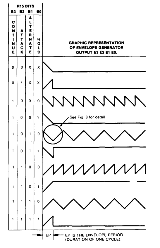
| x | x | x | x | Continue | Attack | Alternate | Hold |
+----+----+----+----+----------+--------+-----------+------+
Bit set (=1) definitions are as follows:
Hold: Limits the envelope to one cycle, holding the last count of the envelope counter
Alternate: Reverses count direction after each cycle
Attack: Count up (attack); otherwise count down (decay)
Continue: Cycle pattern defined by the Hold bit; otherwise reset to 0000 after one cycle and hold
Here's a nice image from the programmer's manual showing this behavior:
The Plan
Given all of this, the plan is to use a microcontroller to interface with the AY-3-8910, probably a simple ATmega328P.
More updates, including a block diagram, to follow!
If you have any questions, comments, or helpful advice feel free to reach out.